Bell Housing Installation Instructions
VP 5.50” BELL HOUSING WITH AN OPEN DRIVELINE
1) Verify you have an 85'-93' Mustang V8 T5 gearbox.
a) Measure the pilot nose of the input shaft. If it measures 17mm (or 0.668") you are good. If it measures 15mm (or 0.590") stop everything, get help, you likely do not have a Mustang V8 T5.
b) Check the spline for correct fit. The custom disk has a Ford Mustang 1 1/16 x 10 spline hub that must match the input shaft spline. If the disk will not slide onto the input shaft, stop everything, get help, you likely do not have a Mustang T5.
c) Measure the distance from the gearbox bolt face to the tip of the input shaft. Use a combo square to get this measurement. If you measured 7 3/16" (+ / - 1/16"), then proceed. If not, get help, changes need to be made.
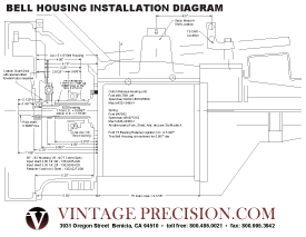
2) Verify Clutch Disk position and fit - Slide the clutch disk onto the gearbox input shaft. The clutch disk must be positioned with the spring retainer hub facing to the rear, toward the gearbox, not the flywheel. Review the drawing to help understand the layout.
a) Slide the disk back as far as possible until it bottoms out on the spline or hits the bearing retainer snout. Measure the distance from the gearbox bolt face to the front side of the friction surface. For the 5.5" Bellhousing with a standard Model A flywheel, the distance must measure less than 4.75". If it is 4.75" or more it will bind the disk to the flywheel at final installation.
b) If the disk hits the Bearing Retainer snout; first - Record the measurement taken to determine how much the snout must be shortened a little later. Second - Remove the disk, then carefully remove the bearing retainer while keeping the input shaft in its proper position. Third - Again slide the disk onto the input shaft (spring retainer hub rearward) until it bottoms against the spline and measure from bolt face to disk front face. If the distance is less than 4.75", you have confirmed that the T5 has the correct input shaft. If the distance is greater than 4.75", you have an input shaft from a later model T5 and it must be corrected to the 85'-93' input shaft.
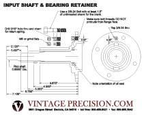
3) Now it's time to modify the Input Shaft and Bearing Retainer. You have confirmed you have the correct T5 with the correct Input Shaft and Bearing Retainer by completing 1 & 2 above. The drawing shows the dimensions that work for the 5.5" Bellhousing.
a) The input shaft will need to have some spline removed by machining. The shaft is hardened, but can be turned with carbide tools. Machine back the spline as illustrated on the drawing. The bottom half of the illustration shows the shaft being 7 3/16" from tip to the main case bolt face with the 17mm pilot diameter transitioning to spline over aprox 5/16" in length. The top half of the shaft drawing shows the modified shaft with a fairly square shoulder and only a 1/16" or less chamfer on the spline teeth only. The object is to have the spline come close to the pilot bearing, but not have the shoulder bottom against the bearing and apply pressure. You can check this before and after machining the shaft by mounting the bellhousing to the motor / flywheel housing / crank / flywheel assembly and inserting the input shaft / bearing retainer assembly into the pilot bearing that is pressed into the flywheel. Push the shaft / retainer assembly (keep the shaft seated in the retainer) forward until the spline shoulder bottoms against the pilot bearing. Then use a straight edge to check the distance from the flange bolt face of the retainer to the bolt face of the bellhousing. When done, the bearing retainer bolt face should be just forward of the bellhousing bolt face by about 1/16". The drawing shows the shoulder being moved to 2.125" from the tip. In reality it might be 2 3/16" or 2 1/8". The pilot diameter should be turned and polished down to 0.6685" dia. Blend the new pilot diameter to the existing diameter.
b) Finally, the tip of the shaft must be shortened so it will not bottom out hitting the recess in the crank. The recess is about ¼" and the shaft will need to have 1 3/8" to 1 ½" of the tip removed. Replacing the center in the shaft is nice but not really necessary. The drawing shows the pilot bearing as mounted in the flywheel and where the shaft is modified. The distance from the nose to the shoulder of the spline should measure 2.188" (2 3/16"). We are splitting hairs here, any shim used to achieve the correct bearing preload in the T5 can make a difference. Best done by machining with carbide tools as far as possible and then cutting the remainder through with an abrasive cutoff wheel. Again, see the drawing to confirm the requirements.
c) Now the bearing retainer - Best to shorten it by turning in a lathe to remove approximately 0.625" (5/8"). The finished length from the bolt flange to the end of the snout should be around 3.88" (3 7/8").
d) Time to machine and install the adapter sleeve for the throw-out bearing. See the drawing for dimensions.
4) Confirm your modifications - Insert the modified input shaft (with bearing) into the Bearing Retainer (with bearing cup and shims).
a) Slide this unit into the pilot bearing that is mounted in the flywheel that is mounted to the crankshaft that is mounted in the motor. In other words, plug the Input Shaft / Bearing retainer unit into the back of the motor and measure the distance from the flywheel friction surface to the Bearing Retainer bolt face. Must be able to insert to measure 4.75". Check clearances around the pilot bearing. Perfect is measuring 4 11/16" when the spline shoulder hits the pilot bearing face.
b) Now remove and slide the Cutch Disk onto the Input Shaft spline and re-install into the motor. Make sure the again the Input / Retainer unit will go forward enough to measure 4 11/16" from bolt face to friction surface of flywheel.
5) Install the Clutch Disk onto the flywheel with the pressure plate assembly. This is a good time to use the input shaft as a pilot shaft for centering the disk while installing the pressure plate before re-installing the Input / Retainer unit back in the gearbox. As you by now have seen, the disk can only go one way.
6) Re-install the Input Shaft and Bearing Retainer back into the T5. Tricky assembly - make sure all 15 needles get into position and don't forget any shims for proper preload.
7) Now the Bellhousing
a) Test fit the Bellhousing into the flywheel housing that is mounted to the motor. Confirm concentricity of T5 register to the flywheel and parallelism of bolt face to flywheel.
b) Measure and confirm 4.75" from the transmission bolt face to the flywheel friction face.
c) Remove the Bellhousing and install the Clutch throw-out shaft assembly. The parts for this are available from Snyders or Bratons or Burts, etc. They are the same as Model A.
d) Fabricate a spring return mount. Look at your Model A bell housing to see the location of the mount to hook the throw-out bearing return spring. You will need to create a mount to attach one end of the return spring in a similar fashion.
e) Install the throw-out bearing. The Throw-out bearing is not the Model A unit. It is the AA truck unit that is shorter in length and is the same as the early Flathead V8 unit. It can be purchased from Speedway Motors in Nebraska or possibly suppliers mentioned above.
8) Having gotten this far, the rest should be a simple re-install, just as installing the Model A tranny as concerns torques, fits, adjustments, etc. WELL ALMOST - You will need to adapt on your own the rest of the driveline to the rear axle, brake mods, e brake mods, etc.
For more information on Vintage Precision's Model A Bell Housing, including installation questions, updated pricing and availability, contact us now by clicking here or call our Customer Service Department at 1-800-486-0021.
If you don't see what you're looking for, let us know. Click Here for any questions or comments.
Home•About Vintage•VP Links•Contact Us
© 2023 www.VintagePrecision.com | Disclaimer
| Terms Of Use